Sorry about the delay in posts, sometimes its just hard finding the time. Hopefully, I will be able to post more frequently in the future.
Today I decided to share a few windows that I made a while back.
These windows don't seem too complex at first glance and rightfully so, when broken down they only contain a few sweeps with a few sets of parameters controlling them.
However, when they are cut in section you can see the detail that went into each window
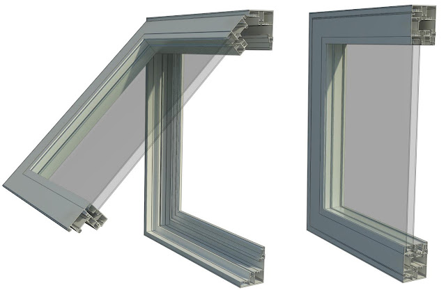 |
| Awning Window: 3D Section |
My main goal for these windows was to test if I could use the actual profiles supplied by the manufacturer, so that not only would the window look good in 3D but would display accuratly in a section view as well
In section these windows look more complex then they actually are, It only took a few easy steps to get the desired result:
First I set up a basic rig using reference planes and set up parameters to control the width, height, and offset from the edge of the wall.
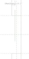 |
| Left Elevation |
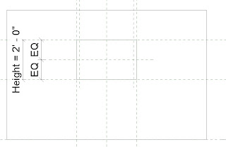 |
| Exterior Elevation |
I then downloaded the profile from the manufacturer and imported the image into the left elevation of the project and scaled it to the approriate size.
I then went to the exterior elevation and created a sweep along the reference planes I created and locked them together.
For the profile of the sweep I traced over part of the manufactures profile getting as close as possible to ensure accuracy
This is the resulting sweep from the profile above:
My next step was to create a reference line with an angle parameter to host the portion of the window that opens. I then repeated the above steps to create the next portion of the window and flexed the parameters to make sure they worked, with the results below:
The final steps included creating the glass which I extruded then constrained to the angle parameter to make sure it followed with the opening of the window and applied the materials and parameters to change them.
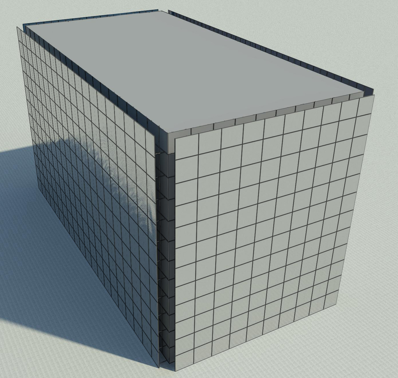
I basically followed the same procedure for the other windows with a few variations in parameters for the double hung and slider windows so I could control the openings. Here are some 3D sections of the other windows I modeled:
Basically what I hope you get from this post is that sometimes it does'nt take that much more work to go the extra mile and create a much more detailed component. By going a little further and using the actual profile supplied by the manufacturer, it creates a more accurate window, and it takes much less time to create an actual architectural section of that wall, (however, it will still need some touching up) while also creating great views when the building is cut in 3D.


.jpg)


.png)

.png)


